Design Features, Mode of Operation
The basic layout of the UZ range of Demag helical-geared air motors is shown by the sectionalized diagram of the UZ 50 motor. All sizes of motor are fundamentally identical with this.
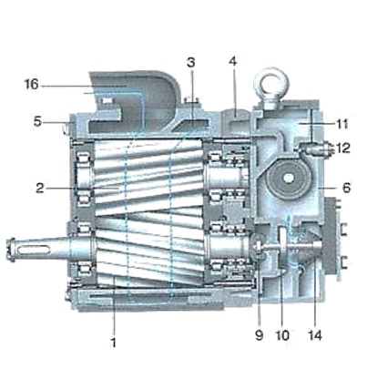
The major components of the motor are the two rotors (1 and 2), the casing (3) with the cover plate (4 and 5) and the control gear casing (6).
The two helically-geared rotors manufactured with maximum care on precision machine tools form the heart of the motor. These rotors are carried in cylindrical roller bearings.
Axial thrust forces are absorbed by two pairs if grooved ball bearings at one end of each rotor. Each pair of these bearings form single unit which is adjusted so that almost all play is taken up

The control gear casing houses the reversing gear, the speed regulator and the automatic oiler for the rotor. The reversing valve (7) for changing the sense of rotation can be actuated by a lever, al delay control (8) or by remote control.
The speed regulator (9), driven by the lower rotor (1), maintains the motor speed constant under all load conditions via the throttle valve (10).
Accomodated in the upper part of the control gear casing is the oil chamber (11) together with the automatic oiler (12) which lubricates the rotor during operations. The air connection (13) can, dependant on the manner in which the motor is installed, be fitted on the right, the left or on the face of the control gear casing. Entry of coarse particles into the air passages prevented by a strainer (14) in the control casing.
Compressed air entering at (13) flows through the strainer (14) and henc to the throttle valve (10) which regulates the motor speed. Via the reversing valve (7) the compressed air then passes to the rotor (1 and 2), which rotate in the sense indicated in the diagram.
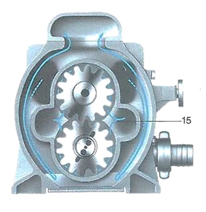
The compressed air passes through the gaps between the teeth of the rotor along the walls of the casing to the discharge passage (15).
The expanding air flows via the reversing valve and the exhaust space (16) into the atmosphere.
To change the sense of rotation, the reversing valve (7) is set in the opposite direction so that the rotors are supplied with compressed air from the other end. If the reversing valve in in the centre position the supply of compressed air is cut and the motor stops
Accessories and Special Equipment.
Demag have developed a wide range of accessories and special equipment for the extremely wide range of applications for which they are employed in a wide range of industries. Each of these items of equipment offer an operationally reliable, safe and economic solution for certain special applications. The large range of special accessories and equipment available substantially expands the potential application of UZ helical-gear air motors and the underlines the advantages of pneumatic drive quite unmistakeably.
Flanged Motor
The standard versions of Demag air motors are all of the foot-mounted (B 3) type. How-ever, they are also supplied as flanged motor of the B 3 / B 5 type. The dimensions of the flange are dictated by the customer´s requirements in each particular instance. The flanged motor ensures accurate centering and eliminates time-consuming alignment of a motor base. A flexible coupling between motor and the driven machine is not absolutely necessary
Slave Control
The slave control for use in conjunction with twin air motor drives was developed from the remote control with zero setting. If a conveyor is driven by two air motors, only one of them need be started up or reversed manually, the second motor automatically following suit. This eliminates any possibility of mistakes being made and the risk of accident is minimized, since the operator does not have to clamber over the conveyer. In many applications electrical remote control of the air motor is to be recommended. The remote control with zero setting is then actuated via electro pneumatic valves controlled from any distance via key switches.
In addition, remote control with zero setting also permits several motors to be controlled simultaneously via electro pneumatic valves from one switch only.
Remote Control
Special control equipment has been developed for mixed multi-motor drives for conveyers. The air motor mounted on the return head is equipped with electro pneumatic remote control and is controlled from the discharge end of the conveyer. As soon as it is started up, the motor immediately rotates in
the required sense; if a second motor is employed, it is started up at the same time via the slave control. The electro pneumatic remote control of the first motor is equipped with a knife switch which is actuated by the piston of the remote control for the motor. After the air motor has started up and the bottom run of the conveyer belt is under tension, a time relay switches on the electric motors at the discharge end of the conveyer. When the air motors are switched off or if the supply of compressed air fails, the knife switch of the remote control is automatically centered in the zero position and the electric motors therefore also switched off.
Silencer
Demag UZ helical-gear motors are practically silent. Design of the exhaust air passages is such that the working noise level is reduced to a reasonable figure. For operational locations where a further reduction in the noise level is necessary for certain reasons, a silencer may be fitted or the exhaust air may be discharged through a special pipe.
Motor Brakes
Suitably equipped, Demag helical-gear air motors may be employed as motor brakes. They can then be employed both for driving and braking machinery. The particular advantage of this Demag method of braking is that excessive heating of the motor, which operates as a compressor during braking, is prevented. Compressed air is fed back into the air system, thus preventing compressed air losses. There are two distinct types of the motor brake, the conveyor motor brake and the hoist motor brake.
The conveyor motor brake is designed for driving continuous conveyors working on the dip. It adapts itself automatically to the operating conditions prevailing at any given time, the operator needing only to switch the motor on and off. The air motor always runs at practically constant speed independent of whether it is driving or braking machine. Changeover from driving to braking is automatic. An additional brake is required for holding the conveyor in the stationary condition.
The hoist motor brake is employed for driving machinery such as, for instance, winding hoists which have to haul loads upwards and brake them when they are descending. When the load is being hoisted, the motor operates as a standard drive motor whereas during braking, as in the case of the conveyor motor brake, it delivers compressed air to the system. The braking device fitted to the motor is actuated by pneumatic remote control. An non-return valve which is part of the braking device can be set to give the desired rope speed during braking.
The Air Motor as Emergency and Standby Drive
The air motor has been proven as a reliable emergency and standby drive in various branches of industry. The following applications are examples of this: In the metallurgical industry for converters, hot metal mixers, lance carriages, holding furnaces, ladle slewing towers and anode furnaces, for lubrication pump units and equipment in the petrochemical industry as well as for driving coke-oven ejection equipment.
The advantage of the air motor is that after the electric power supply has failed, it can be powered from a compressed air accumulator. The special control equipment is matched to suit the appropriate operating conditions. For monitoring and controlling drives for converters and similar equipment, Demag have developed an automatic safety control system. It takes over control of the plant if, for example, the minimum pressure in the blowing main for converters or in the compressed air system for other equipment is undershot, and it also takes over in the event of power failure (compressor and / or main drive).
This control equipment actuates the air motor and holding brake and travels the equipment from the hazard position into the safety position. During this process the control equipment is interlocked, so that external interference is not possible. In addition, the operating personnel is warned by an acoustic signal.
Main Drive for Converters
The converter main drive consists of a remotely controlled air motor with reduction gearing. After the motor has been switched off, the converter is locked in position by a holding brake actuated by compressed air and controlled by the motor control equipment. The control equipment shown in the diagram below is connected to the converter gearing in such a way that the cam feeds the converter motion into the safety control equipment. In normal operation, the pressure of the medium employed for blowing maintains the weight-loaded piston of the safety control equipment in the top position and permits normal manual control.
During emergency operation, i. e. After the pressure of the blowing medium has fallen below a certain adjustable value or if there is a power failure, the weight-loaded piston drops into the lower position. The safety control equipment the automatically switches on the air motor, which travels the converter from the blowing position (hazard position) into the charging positions (safety position). This means that when the supply of blowing air fails, the blowing nozzles are above the top of the bath and are therefore no longer at hazard.
Emergency Drive for Converters
The main drive of the converter is by electric motor connected to the converter gearing via a coupling. The emergency drive consists of an air motor with holding brake which is also connected to the converter gearing by a pneumatically – controlled clutch. The safety control equipment is directly coupled to the converter gearing or direct to the converter. In normal operation the emergency drive is switched off by safety control equipment. During emergency operation, i. e. After the pressure of the blowing medium has fallen below the set value or in the event of power failure, the safety control equipment responds as already described. The main electric drive is separated from the mains and the automatically actuated emergency pneumatic drive travels the converter into the safety position. In this position the holding brake is engaged and the plant is automatically switched off. Within the safety range, the converter can be travelled by the air motor, i. e. It may be discharged by this means.
